Screening & Qualification for Harsh Environments
SCREENING AND QUALIFICATION
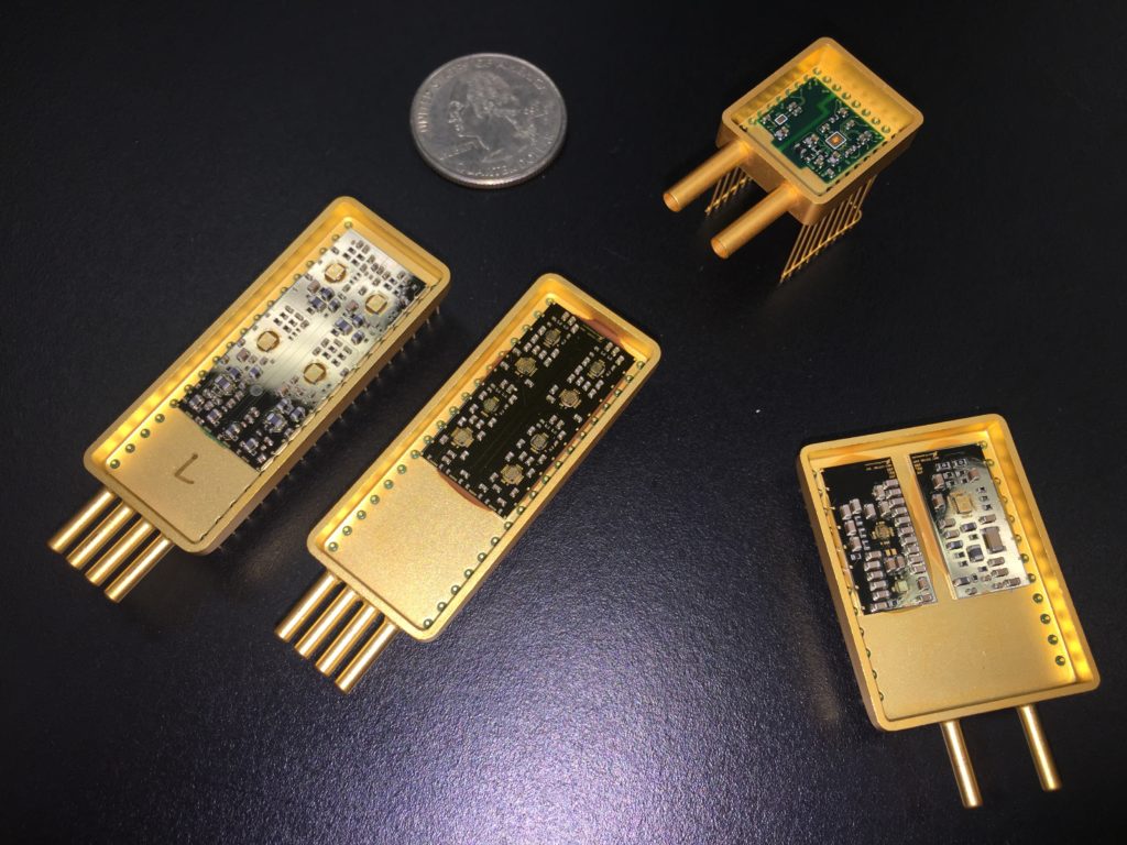
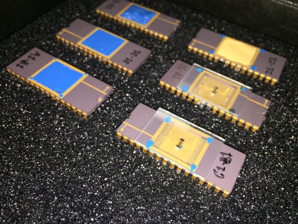
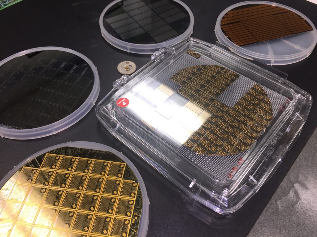
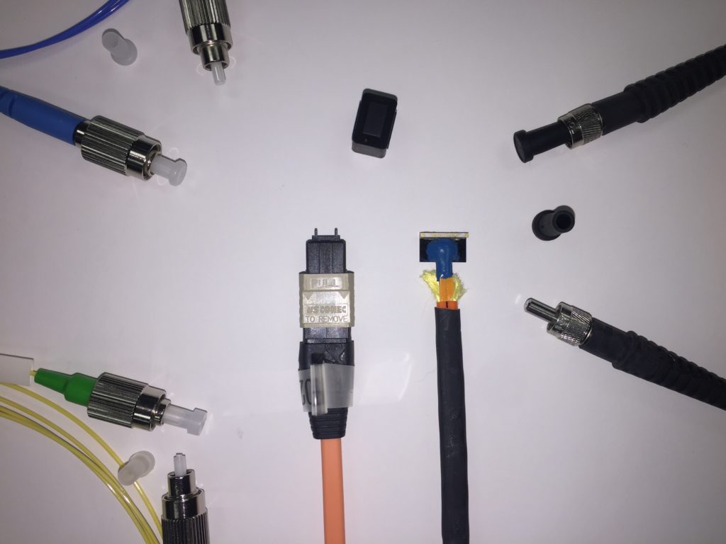
Nanomatronix provides testing, evaluation and engineering services for the defense industry, and we have the technical expertise, accreditation and infrastructure needed to meet the needs of our customers in both the public and private sectors. Our team possesses a unique mix of interdisciplinary knowledge and experience designing, prototyping, producing, screening, and characterizing a variety of ruggedized, hybrid microelectronics and optoelectronics components (examples pictured below) for harsh environments. Nanomatronix strictly adheres to National Industrial Security Operating Manual (NISPOM) regulations, and are accredited to a wide range of regulatory standards. Let us help you navigate the often confusing world of Qualified Manufacturers List (QML)/non-QML Screening and Qualifications (S&Q) test requirements.
Service Capabilities
The “burn-in” test involves exercising system components prior to being placed in service, often prior to full system assembly. The testing process forces certain failures to occur under controlled and supervised conditions to establish an understanding of load capacity of the product. There is a portion of failures occurring early in the life of a set of components; burn-in helps to detect these. For sufficiently long (and, perhaps, artificially stressful) burn-in periods, the system can then be trusted to be largely free of additional early failures occurring after the burn-in process has been completed. Replacing weak components that fail during burn-in may help prevent premature system failure, infant mortality failure, or other latent defects.
See the standard documentation for more information on test requirements, conditions, and procedures related to your application.
As per MIL-STD-883E, Method 1014.9, the purpose of this test is to determine the effectiveness (hermeticity) of the seal of microelectronic and semiconductor devices with designed internal cavities.
See the standard documentation for more information on test requirements, conditions, and procedures related to your application.
Similar to hot/cold storage, start tests involve subjecting components to extreme heat and/or cold. These tests, however, require operating the components during exposure to the extreme conditions.
See the standard documentation for more information on test requirements, conditions, and procedures related to your application.
Hot/cold storage tests involve subjecting devices to hot/cold temperature extremes for an extended period with the devices maintained nonoperational. One purpose of the tests in this area is to determine whether optoelectronic devices can withstand the high and low temperatures encountered during transportation and storage. Thus, the devices do not operate during these tests, but appropriate functionality measurements need to be made before and after the tests.
In the case of low temperatures, few failure mechanisms related to long-term storage have been observed, and therefore a relatively short-term test that is consistent with the low-temperature storage test described for systems in GR-63-CORE (i.e., 72 hours at -40°C or the minimum specified storage temperature, whichever is lower) is considered sufficient. Conversely, a relatively long-term test (i.e., 2000 hours at +85°C or the maximum specified storage temperature, whichever is higher) is specified for high-temperature storage. The reason for this is that in some cases this test has been found to stimulate failure modes in much the same manner as a high-temperature operations test (which is also a relatively long-term test). On the other hand, if the failure mechanisms that are relevant under high-temperature conditions are not significantly affected by whether or not the device is operating, then the high-temperature storage and operations tests may be redundant, and only the more stressful of those two tests may need to be performed (see Section 3.3.3.1.3 of the GR-468 CORE Document). Refer to the GR-468-CORE document for additional details if needed.
See the standard documentation for more information on test requirements, conditions, and procedures related to your application.
As per MIL-STD-883E, Method 2002.3, the shock test is intended to determine the suitability of the devices for use in electronic equipment which may be subjected to moderately severe shocks as a result of suddenly applied forces or abrupt changes in motion produced by rough handling, transportation, or field operation. Shocks of this type may disturb operating characteristics or cause damage similar to that resulting from excessive vibration, particularly if the shock pulses are repetitive.
The system employed by Nanomatronix develops the kinetic energy electromagnetically. An iron core “bullet” is attracted to the magnetic core of a solenoid by the dense magnetic field that is created as current flows through the field coil of the shock tower. As the bullet is drawn into the center of the magnetic field the acceleration increases exponentially as the gap reduces to zero on impact causing the high impact shock. The properties of the impacting materials determine the pulse shape and duration.
See the standard documentation for more information on test requirements, conditions, and procedures related to your application.
As per MIL-STD-883E, Method 2009.9, external visual inspection is primarily used to verify the workmanship of hermetically packaged devices. This method is used to inspect for damage due to handling, assembly, and/or test of the packaged device.
As per MIL-STD-883E, Method 2012.7, the purpose of radiographic examination is to nondestructively detect defects within the sealed case, especially those resulting from the sealing process and internal defects such as foreign objects, improper interconnecting wires, and voids in the die attach material or in the glass when glass seals are used. It establishes methods, criteria, and standards for radiographic examination of semiconductor and hybrid devices.
See the standard documentation for more information on test requirements, conditions, and procedures related to your application.
Particle Impact Noise Detection (P.I.N.D.) is a reliability screening technique that employs vibration, shock, and acoustics to detect potentially detrimental loose particles that have the potential of causing short circuits within electronic components and serious malfunctions in system operations. As a requirement for MIL-STD883E, MIL-STD750, and MIL-STD39016, this test has helped the manufacturers of hermetically sealed electronic components greatly increase product reliability over the past thirty years by detecting contaminants within the cavity. Recent advancements in packaging methods have created significantly larger, heavier packages, requiring improvements to test equipment. These include advancements to the closed loop control of vibration, increased dynamic range of closed-loop shock control, and the addition of multiple crystal acoustic sensors.
Our non-destructive, high frequency acoustic test detects loose particles moving inside high-reliability, internal cavity electronic components such as relays, transistors, hybrids, integrated circuits, and switches. A shaker is used to excite loose particles within the component cavity. Upon striking the lid of the cavity, some of the particle energy is converted to a wide-band pressure wave that travels through the lid to be detected by the sensitive ultrasonic sensor to which the device under test is attached. To keep the particle moving, a very accurate shock is employed, generated internal to the shaker and feedback-controlled by electronics monitoring the motion of the sensor.
See the standard documentation for more information on test requirements, conditions, and procedures related to your application.
The objectives of radiation characterization tests are to demonstrate/validate acceptable survival and operational performance boundaries of components. The capability of each component to operate/survive in each applicable radiation environment shall be assessed with respect to degradation in performance and respective survival rates. Assessment of successful post radiation performance shall include verification of functional capability at intermediate dose levels below rated dose and beyond (minimum of 50% above rated TID and/or Displacement Damage (DD) of the device or failure, whichever is lower). When DD and TID environments apply, the above stated verification of functional capability shall be performed on separate samples and their effects.
See the standard documentation for more information on test requirements, conditions, and procedures related to your application.
Random and constant or swept sinusoidal frequency tests are the typical methods of vibration testing.
Random Vibration: As per MIL-STD-883E, Method 2026, this test is conducted for the purpose of determining the ability of the microcircuit; to withstand the dynamic stress exerted by random vibration applied between upper and lower frequency limits to simulate the vibration experienced in various service-field environments. Random vibration is more characteristic of modern field environments produced by missiles, high-thrust jets, and rocket engines. In these types of environments, the random vibration provides a more realistic test. For design purposes, however, a swept frequency sinusoidal test may yield more pertinent design information.
Sine vibration testing uses a single frequency to excite resonances within the device under test. In swept sine tests, the vibration sinusoidal tone is ramped up and down through a frequency range for a specific duration. This method is primarily useful for detecting resonant conditions within test devices. It can be useful to identify or simulate worst-case fatigue exposure by finding resonant frequencies of the test item. The most damaging stress conditions for the device can typically be obtained by conducting such a resonant frequency vibration test with increased amplitude.
See the standard documentation for more information on test requirements, conditions, and procedures related to your application.
As per MIL-STD-883E, Method 1005.8, the steady-state life (SS-Life) test is performed for the purpose of demonstrating the quality or reliability of devices subjected to the specified conditions over an extended time period. Life tests conducted within rated operating conditions should be conducted for a sufficiently long test period to assure that results are not characteristic of early failures or “infant mortality,” and periodic observations of results should be made prior to the end of the life test to provide an indication of any significant variation of failure rate with time. Valid results at shorter intervals or at lower stresses require accelerated test conditions or a sufficiently large sample size to provide a reasonable probability of detection of failures in the sample corresponding to the distribution of potential failures in the lot(s) from which the sample was drawn.
See the standard documentation for more information on test requirements, conditions, and procedures related to your application.
As per MIL-STD-883E, Method 1010.7, this test is conducted to determine the resistance of a part to extremes of high and low temperatures, and to the effect of alternate exposures to these extremes.
See the standard documentation for more information on test requirements, conditions, and procedures related to your application.
Thermal vacuum testing is typically performed as a method to understand and measure the operation of spaceflight components under simulated space and upper atmosphere conditions, as the temperature can be controlled while subjecting components to varying levels of vacuum.
See the standard documentation for more information on test requirements, conditions, and procedures related to your application.
Equipment
Nanomatronix has the following equipment within our facilities. This equipment is used for the services listed above.


The Delta Design 9000 Series Temperature Chambers offer a wide choice of temperature ranges and capacities in addition to smart electronics. Nanomatronix utilizes multiple 9064 and 9076 models with the following capabilities.
9064:
- Internal Chamber Dimensions: 2.2 cubic feet (12″H × 20″W × 16″D) (62.3 liters)
- Temperature Range: -73° to +315°C (-100°F to +600°F); -184°C (-300°F) with optional LN2
- Heat-up Rate: 8°C / minute
- Cool-down Rate: 20°C / minute
- Air Circulation: vertical air flow pattern
9076:
- Internal Chamber Dimensions: 5.78 cubic feet (20″H × 20″W × 25″D) (163.7 liters)
- Temperature Range: -73° to +315°C (-100°F to +600°F); -184°C (-300°F) with optional LN2
- Heat-up Rate: 8°C / minute
- Cool-down Rate: 12°C / minute
- Air Circulation: horizontal air flow pattern

The TestEquity 3007C FastRate™ Temperature Chamber used by Nanomatronix has the following relevant capabilities:
- Internal Chamber Dimensions: 7 cubic feet (24″W × 21″H × 24″D) (198 liters)
- Temperature Range: -73°C to +175°C
- Ramp Rate: Over 10°C / minute without LN2; Optional LN2 boost cooling

This chamber has similar specifications to the TestEquity chambers; however, the Tenney is currently used exclusively for elevated temperature Burn-in, SS-Life and 85/85 (Moisture Resistance).
- Internal Chamber Dimensions: 10 cubic feet (24″W × 27″H × 25″D)
- Temperature Range: -73°C to 177°C
- Humidity Range: 20% to 95% relative humidity

The thermal vacuum system is LN2-cooled and heated by molded-in tubular heating elements. The thermal vacuum system is set up with a Leybold TMP – 1000C turbo pump or an optional larger model. Thermal processing is controlled using a Watlow temperature controller. The system includes an LN2 control solenoid, vacuum ion gauge, and electrical controls. The Watlow controller runs a programmable temperature profile to take the platen down to -150 oC and then up to +150 oC at about 3 oC/min.

The Spectral Dynamics SD-220-120M Vibration Test System is a 220 lbf shaker with a 5 – 6000 Hz frequency range. Spectral Dynamics SD-220-120M shakers are designed to test small to medium sized payloads and possess design features that meet testing requirements of the automotive, aviation, military, medical and electronic manufacturing industries. The system consists of a model SD-220-120M shaker and is driven by the Model SPA102B power amplifier and a 0.75 KW cooling blower.

Capable of up to 110 lbs. force, the 3-inch diameter armature table is suitable for loads that require high vibration levels. The shaker’s full 1-inch armature stroke capability is ideal for many modal as well as low and high frequency general applications. The air cooled PA-141 linear amplifier is direct coupled to the shaker to give the maximum performance at low and high frequencies and can be easily switched from voltage source mode, for general testing, to current source mode for modal testing applications.

BW-MST-E5000 Mechanical Shock Test System
Modern electronic devices must endure the effects of repetitive mechanical shocks and sustain operation to achieve customer satisfaction. The BW-MST-E5000 is designed to produce these high impact shocks associated with dropping a device. Technical specifications include shock duration of 0.2 – 2.0 ms, pulse output of 0 – 5000 G peak, sine (Pk) of 2000 lbf, stroke of 1 inch, and velocity of 240 in/s

Nanomatronix uses a SD Model 4511M PIND system from Spectral Dynamics, Inc. Combining sensors that monitor and display the shaker motion with computer control to correct for any changes in test conditions, the SD PIND test system generates accurate and repeatable test conditions. Its ultra-sensitive, ultrasonic (155 kHz) sensor with multiple crystals can detect particles as smaller than 15 microns in diameter impacting the package cavity.

Nanomatronix uses an IsoVac Radiflo® Mark VI Pressurization Unit to perform hermeticity tests. This state-of-the-art radioisotope leak detector is capable of reaching test sensitivities less than 1×10-11 atm-cc/sec; it can meet and exceed any of your gross or fine leak-testing needs. Krypton-85 is the radioactive gas used in product seal tests. The quantities of radioactive Krypton-85 used in our system are extremely low. Typically the Kr-85 gas is less than 0.01% of the total nitrogen or air in the machine.

The JewelBox-90T delivers precision x-ray images of ultra-high resolution and grey scale accuracy without the aberrations of voltage blooming and pincushioning prevalent in other systems. The JewelBox-90T uses a powerful 90kV micro-focus x-ray tube for deep penetration of dense materials, including metal BGAs. The camera’s sensitivity allows imaging of low-density materials such as plastics, polymers, collagen and urethanes, as well as very small parts fabricated from ceramics and titanium.
Standards and Certifications
Novel hybrid and monolithic microcircuits are becoming more prevalent in emerging aerospace, space and other harsh environment systems. Most suppliers of these emerging components and sub-systems are non-QML manufacturers and therefore require a significant level of product assurance and quality control scrutiny from their buyers.
The Nanomatronix Microelectronics Strategic Business Unit (SBU) was established to assist our customers (the non-QML suppliers and buyers) with the development and execution of compliant, standardized screening and qualifications test plans per relevant DOD, NASA and industry standards. The following list is a partial list of applicable standards, specifications, and certifications that Nanomatronix can meet.
| Standard/Specification | Title |
|---|---|
|
MIL-HDBK-340 |
Test Requirements for Launch, Upper-Stage, and Space Vehicles |
|
MIL-PRF-32383 |
General Specification for Batteries, Rechargeable, Sealed |
|
MIL-PRF-38534 |
General Specification for Hybrid Microcircuits |
|
MIL-PRF-38535 |
General Specification for
Integrated Circuits (Microcircuits) Manufacturing |
|
MIL-PRF-49291 |
General Specification for Fiber, Optical: Type 1, Class 1, Composition A, Size 3, Wavelength B, Radiation Resistant |
|
MIL-STD-461 |
Electromagnetic Interference Characteristics Requirements for Equipment |
|
MIL-STD-750 |
Test Methods for Semiconductor Devices |
|
MIL-STD-883 |
Microcircuits Test Methods Standard |
|
MIL-STD-1678 |
Fiber Optics Test Methods and Instrumentation |
|
MIL-STD-810 |
Environmental Engineering Considerations and Laboratory Tests |
|
EEE-INST-002 |
Instructions for EEE Parts Selection, Screening, Qualification, and Derating |
Ask about our various other industry and customer specified standards
| Certifications | Title |
|---|---|
|
IPC J-STD-001 |
Requirements for Soldered Electrical and Electronic Assemblies and Space Applications Electronic Hardware |
|
ANSI/ESD S20.20 |
Electrostatic Discharge Safety |
|
NASA-STD-8739.1 – 8739.5 |
Requirements for Polymeric Applications, SMT, SEC, CCH, and FOT |
|
AS-91000 Compliant |
Quality Management System Standard Compliant |
Contact us
We’re here to answer any questions you might have. We look forward to hearing from you.
Interested in working with us? Tell us about your project!