Optoelectronics Characterization
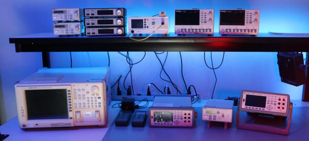
Equipment
- Instek GPD 4303S Programmable Power Supply
- Arroyo 5240 TEC Current Source
- Ando AQ6317B Optical Spectrum Analyzer
- Keysight N9952A RF/MW Vector Network and Spectrum Analyzer
- Keysight 34461A Digital Multimeter
- Thorlabs MX10C High-Speed Optical Transmitter, C-Band Laser, Phase Modulator
- Thorlabs S146C Optical Power Meter
- Thorlabs ERM 100 Polarization Extinction Ratio (PER) Meter
- Thorlabs LDC 200C Laser Diode Controller and Current Source
- Optotest OP940 Optical Insertion Loss (IL) and Return Loss (RL) Meter
Service Capabilities
Common-mode rejection is the ability of an amplifier to eliminate the common-mode voltage from the output. The ideal amplifier would remove all of the common-mode signal, or the voltage common to both sides of the differential pair. Common-mode voltages can come from numerous sources, including an ambient radiated signal, an offset from signal common created by the driver circuit, or a ground differential between the two ends of the circuit. Regardless of its cause, it’s not the common-mode voltage that’s of interest, but rather the differential voltage. Thus, the measure of how good the differential amplifier is at getting rid of common-mode voltage is its common-mode rejection ratio (CMRR).
The device-under-test (DUT)’s threshold current is the minimum current at which the optical output is dominated by stimulated emissions rather than spontaneous emissions. Along with the DUT’s threshold current and corresponding optical output power level, the forward voltage at threshold VF(TH) can be an important parameter to be specified and measured in the characterization process.
Dark current is the relatively small electric current that flows through photosensitive devices such as a photomultiplier tube, photodiode, or charge-coupled device even when no photons are entering the device; it consists of the charges generated in the detector when no outside radiation is entering the detector. It is referred to as reverse bias leakage current in non-optical devices and is present in all diodes. Physically, dark current is due to the random generation of electrons and holes within the depletion region of the device.
DC bias Vπ is the DC voltage applied through the pins to cause a 180 degree (π) phase shift in the MZ (Mach Zehnder) structure. The modulator’s optical output power will go through minimum to maximum by one Vπ. The minimum does not have to be at 0 Volt. To operate the modulator, one first sets the DC port bias (either positive or negative voltage) so that the optical transmission is at the peak, or null, or quadrature point; then apply the RF voltage. If it is set at minimum, the peak can occur at +/- Vπ.
Photodiode conversion efficiency refers to how a change in optical power is converted to a change in output electrical current. As the frequency of modulation increases, eventually the receiver conversion efficiency will roll off. Thus, the device has a limited modulation bandwidth. The measurement of modulation bandwidth consists of stimulating the photodiode with a source of modulated light and measuring the output response (RF or microwave) current with an electrical receiver. Normally the frequency of the modulation is swept to allow examination of the photodiode or optical receiver over a wide range of modulation frequencies.
Optical time domain–based measurement spatially evaluates back-reflection characteristics both in individual components and along the length of a fiber. One main instrument that uses this measurement method is the optical time-domain reflectometer (OTDR). An OTDR measures the backscatter level of the fiber medium itself and the peak reflection level of Fresnel events along an optical link. IL/RL meters are a form of OTDR. The backscatter measurement level is a function of the fiber backscatter coefficient—an intrinsic factor of the fiber under test— and the pulse width used for measurement.
The optical null depth is essentially the same as the ‘on/off’ extinction ratio, calculated in dB as -10 * log (optical power @ null/ optical power @ peak). For example, -10 * log (0.01mW/1mW) = -10 * log (0.01) = 20 (dB).
The optical null depth is essentially the same as the ‘on/off’ extinction ratio, calculated in dB as -10 * log (optical power @ null/ optical power @ peak). For example, -10 * log (0.01mW/1mW) = -10 * log (0.01) = 20 (dB).
Optical output power is measured using a calibrated optical meter that has detection range within the specified laser diode modules transmit wavelength and output power. In the event that the transmit output power is higher than the upper limit of the detector, a calibrated attenuator and fiber patch cable will have to be utilized. The fiber pigtail/connector is inspected and cleaned as needed, then connected to the power meter (AVIM-to-FC adapter). Power is applied to the laser transmitter module and the optical output power is measured directly in mW, W and/or dB.
Optical time domain–based measurement spatially evaluates back-reflection characteristics both in individual components and along the length of a fiber. One main instrument that uses this measurement method is the optical time-domain reflectometer (OTDR). An OTDR measures the backscatter level of the fiber medium itself and the peak reflection level of Fresnel events along an optical link. IL/RL meters are a form of OTDR. The backscatter measurement level is a function of the fiber backscatter coefficient—an intrinsic factor of the fiber under test— and the pulse width used for measurement.
The polarization extinction ratio (PER) is the ratio of optical powers of perpendicular polarizations, usually called TE (transverse electrical) and TM (transverse magnetic). The PER is used to characterize the degree of polarization in a polarization-maintaining device or fiber. For coherent transmitter and receiver, the PER is a key parameter, since X polarization and Y polarization are coded with different signals.
Component power consumption is a relatively simple and straight-forward test in which the device-under-test (DUT) is powered-on, is operating normally (or at stressed environmental conditions), and the current (I) and voltage (V) are being monitored to confirm total power consumed per Ohm’s Law (V=IR and P=IV). This may be monitored over time (I-V curve) or at a particular instance in time. For the Laser Diode (LD) modules this includes confirming component power consumption for the laser diode, integrated TEC and external TEC.
Responsivity measures the input–output gain of a detector system. In the specific case of a photodetector, responsivity measures the electrical output per optical input. The responsivity of a photodetector is usually expressed in units of either amperes or volts per watt of incident radiant power. For a system that responds linearly to its input, there is a unique responsivity. For nonlinear systems, the responsivity is the local slope. Responsivity is a function of the wavelength of the incident radiation and of the sensor properties, such as the bandgap of the material of which the photodetector is made.
Once the photodiode has converted the modulated light to a proportional electrical current, the task is then to efficiently transmit the demodulated signal to any following electrical components. High-speed systems usually require this transfer over 50 or 75 Ω transmission lines. The output impedance of a photodiode is usually much higher than 50 Ω (or 75 Ω). This leads to the possibility of signal reflections and degraded conversion efficiency. If the signal transmitted from the photodiode encounters another impedance mismatch along the transmission path, energy will be reflected back towards the photodiode. The energy will then be rereflected in the forward direction and potentially interfere with primary signals. Thus, reflections can lead to communication degradation.
SMSR is the ratio (typically in dB) of the average optical power in the dominant longitudinal mode of an SLM laser to the optical power in the next most significant mode.
Laser module transmit wavelength is measured using an optical spectrum analyzer (OSA). OSA’s are general-purpose instruments that measure optical power as a function of wavelength. These OSA instruments are versatile enough to analyze broadband optical signals, resolve the Fabry-Perot modes of a gain chip, and identify gas absorption lines in a spectral measurement.
Contact us
We’re here to answer any questions you might have. We look forward to hearing from you.
Interested in working with us? Tell us about your project!